The problem we set out to solve
PV panels and fuel cells commonly produce less than 50 V, so their output must be stepped up substantially before it can supply a useful DC bus. Interleaving, coupled inductors, and voltage-multiplier cells can produce that gain at moderate duty cycles, but established high-gain designs repeatedly trade one desirable property for another.
- Some converters require both high duty cycles and many components, increasing conduction loss.
- Multiple switches used for interleaving or soft switching complicate the control system.
- Placing a coupled inductor directly at the input creates pulsating, high-ripple current that is poorly suited to PV panels and fuel cells.
- Several converters need complicated control to recover leakage-inductance energy.
- Some multistage or multi-input approaches introduce circulating current and additional power loss.
We wanted a family of single-switch converters capable of ultra-high gain at low duty cycle, continuous input current, comprehensive energy recycling, and simple control.
The core idea
The paper introduces four related converters—Pro1 through Pro4—built around a center-tapped coupled inductor. Each version extends the same energy-transfer concept, allowing designers to choose a topology that matches the required gain and component complexity. Pro4 is the most complete version and the one validated in hardware.
- One coupled inductor with several energy-recycling paths. Each converter combines a two-, three-, or four-winding center-tapped coupled inductor with an input inductor, an intermediate-link capacitor, a switched capacitor, and diodes. Magnetizing and leakage energy is transferred through capacitive and inductive paths to the output rather than dissipated.
- High gain at low duty cycle. Pro4 divides its output across two ports, Co1 and Co2. This distributes voltage stress across two groups of components while gain rises steeply with duty cycle and turns ratio.
- One switch and simple control. Every family member uses one active switch and only two continuous-conduction operating modes, requiring a single pulse-width-modulated gate signal.
- Continuous low-ripple input current. A dedicated front-end inductor smooths the source current. Analysis shows that maximum ripple occurs below a duty cycle of approximately 0.3, outside the D > 0.4 range normally used for high step-up operation.
What we built and tested
We built a 1.25 kW Pro4 prototype and validated it at 1014 W measured output, using a 30 V input, 50 kHz switching frequency, and coupled-inductor turns ratios of 2.
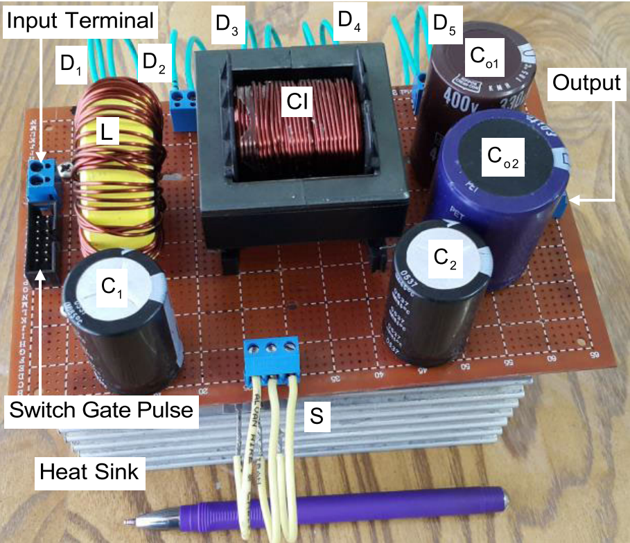
- Intermediate-link capacitor, switch, and diode voltages closely matched the theoretical stress equations.
- Switching waveforms showed none of the large voltage spikes often associated with high-gain coupled-inductor converters.
- Input-current ripple was approximately 10% peak-to-peak.
- The two output-capacitor voltages measured 220 V and 556 V, close to the predicted 225 V and 562 V.
- Efficiency increased smoothly from approximately 89.2% at light load to a peak of 95.94% near full load.
Across comparison groups organized by coupled-inductor winding count, the proposed family consistently delivered the highest gain for a given duty cycle or turns ratio, low normalized switch-voltage stress, fewer components, lower input-current ripple, and fewer operating modes than most alternatives.
Why this matters
Wide output range, low input-current ripple, recycled magnetic energy, and simple single-switch control are rarely available together. This converter family uses the center-tapped coupled inductor as a common building block across four related topologies, giving designers a practical way to select the winding count, gain, cost, and complexity most appropriate for a PV or fuel-cell system.