The problem we set out to solve
PV panels and fuel cells produce low DC voltage, while their applications often require several hundred volts. Many established techniques can produce high gain—cascaded stages, coupled inductors, switched capacitors and inductors, and voltage-multiplier cells—but combining them without creating new compromises is difficult.
Input-current quality was one of the most persistent tradeoffs. A converter that draws pulsating, high-ripple current reduces efficiency, disrupts the maximum-power-point tracking used by PV and fuel-cell systems, and places additional stress on the source.
- Some high-gain converters were not designed with a current-fed input, leaving their source current discontinuous or pulsating.
- Placing the source in series with a coupled inductor can introduce substantial input-current ripple.
- Interleaving reduces ripple but typically duplicates active and passive components, lowering efficiency and increasing complexity.
- Some low-component-count coupled-inductor designs provide only modest voltage gain.
- Other switched-capacitor high-gain converters require more components and a more complex controller.
We wanted a converter that would produce smooth, continuous input current by design, achieve ultra-high voltage gain, and retain simple control with a modest component count.
The core idea
The converter combines one input inductor, two two-winding coupled inductors, three capacitors, four diodes, and two switches driven by one shared gate pulse.
- A genuinely current-fed front end. The source always supplies current through a dedicated input inductor rather than through a coupled inductor or discontinuous switching path. This keeps input current continuous and low-ripple throughout the operating range—the behavior preferred by PV maximum-power-point tracking and fuel cells.
- Two coupled inductors provide two independent turns ratios. The two separate two-winding magnetic components allow the voltage gain to be shaped using duty cycle and two turns-ratio parameters, covering a wide output range without adding conversion stages.
- Both switches use one gate pulse. The two power switches turn on and off together. Combined with only two main continuous-conduction operating states, this keeps the drive and control system exceptionally simple for a two-switch high-gain converter.
We also analyzed continuous, boundary, and discontinuous conduction modes so that the design guidance covers the converter’s full operating range rather than only its ideal continuous-current case.
What we built and tested
We built a 200 W laboratory prototype that raised a 17 V input to approximately 440 V—a voltage gain near 26—at a duty cycle of 0.5 and a switching frequency of 50 kHz.
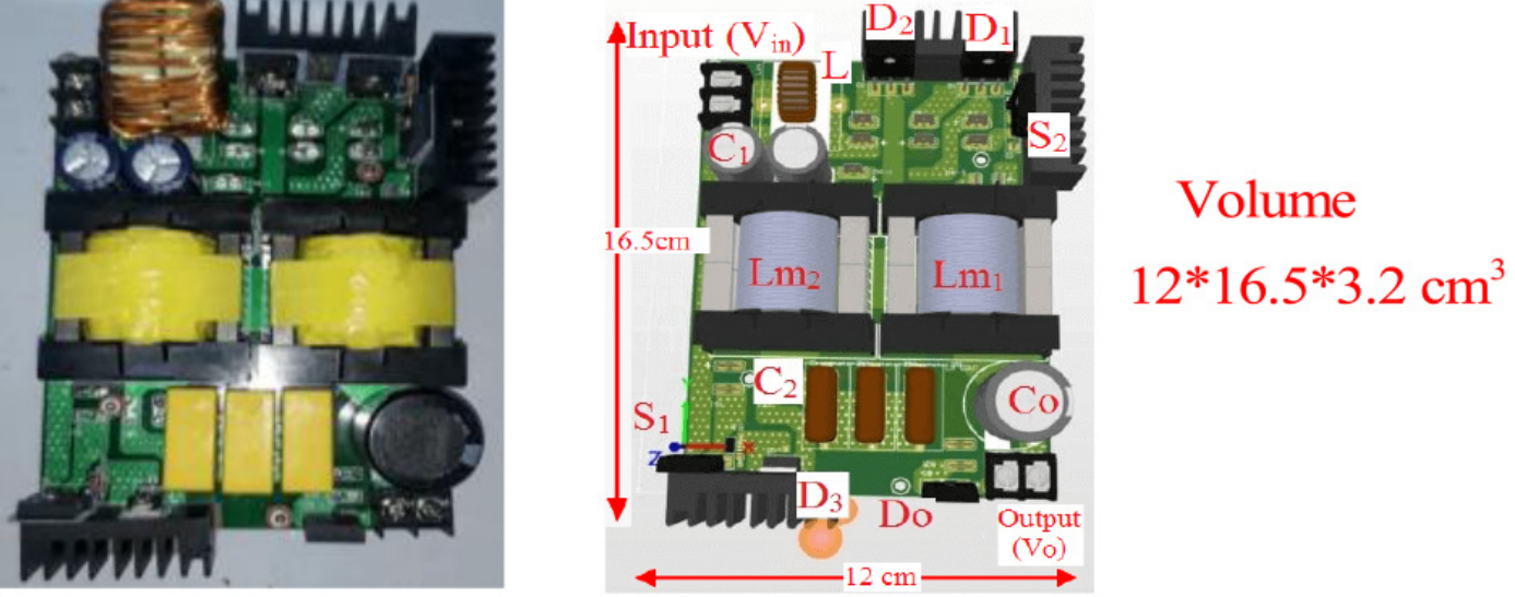
- The measured output was approximately 440 V, closely matching the theoretical voltage-gain equation.
- Input current remained continuous and low-ripple, while switch and diode voltage and current waveforms agreed closely with the calculated device stresses.
- Measured efficiency at 200 W was 94%.
- The input inductor and two coupled inductors accounted for approximately 6.8 W of losses, the diodes about 4.2 W, and the switches and capacitors comparatively little.
Against recent two-coupled-inductor high-gain designs, the converter matched or exceeded most alternatives in voltage gain above a duty cycle of approximately 0.35. Its accumulated switch-voltage stress was lower than all but two compared designs, both of which achieved noticeably less gain. It also tied for the fewest operating modes in the comparison.
Why this matters
For sensitive low-voltage sources—especially PV arrays and fuel cells—input-current quality directly affects both usable energy extraction and source lifetime. This converter demonstrates that a genuinely current-fed, low-ripple input can be combined with ultra-high voltage gain and a simple single-pulse control scheme without resorting to interleaving or a large component count.