The problem we set out to solve
PV panels and fuel cells produce low DC voltage that must be raised substantially before it becomes useful. A conventional boost converter reaches very high gain only with an extreme duty cycle, which creates heavy conduction losses. Voltage-multiplier cells, coupled inductors, switched capacitors, and cascaded stages can increase gain, but each technique introduces its own compromises.
Across recently published high-gain converters, several recurring tradeoffs stood out:
- Some single-switch passive-clamp designs maintained low losses and switch stress only by accepting limited voltage gain.
- Interleaved coupled-inductor converters achieved higher gain but required extra switches for soft switching.
- Converters that achieved soft switching without extra switches often delivered only modest gain.
- Some designs reduced switch-voltage stress while leaving every diode hard-switched.
- Coupled inductors placed directly at the input often created the high input-current ripple that PV panels and fuel cells should avoid.
- Other designs reduced input ripple by adding many components or restricting the usable duty-cycle range.
We wanted ultra-high gain from a single switch, full soft switching for both the switch and diodes, and continuous low-ripple input current—without adding more switches or a large component count.
The core idea
The UHFSC converter combines a single active switch, one three-winding coupled inductor, and two resonant tanks.
- A truly single-switch, fully soft-switched design. A primary resonant inductor-capacitor tank provides zero-current turn-on and zero-voltage turn-off for the main switch. A second resonant path, using the coupled inductor’s leakage inductance, extends zero-current switching to nearly every diode, including the output diode, suppressing reverse-recovery loss.
- Two integrated voltage-multiplier cells. The secondary and tertiary windings of the coupled inductor each feed a voltage-multiplier cell. Two independent turns ratios shape the gain, producing ultra-high output voltage at a moderate duty cycle without separate cascaded stages.
- Leakage energy is reused. Energy in the coupled inductor’s leakage inductance supports resonance and is recycled to the output through a passive clamp instead of producing voltage spikes or being dissipated.
- Switch stress does not scale with turns ratio. The coupled-inductor turns ratios can increase voltage gain without increasing the switch-voltage stress, enabling a low-voltage, low-resistance device to be used.
- Input current remains continuous. A dedicated input inductor keeps the source current smooth and low-ripple, supporting PV and fuel-cell efficiency and longevity without isolated current-feedback sensors.
What we built and tested
We built a 200 W prototype that raised a 20 V input to approximately 385 V at a duty cycle of 0.5, a coupled-inductor turns ratio of 2.5, and a switching frequency of 50 kHz.
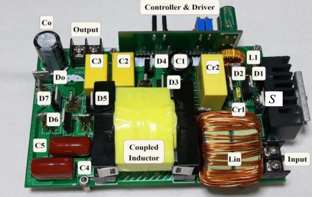
- Measured output voltage closely followed the theoretical gain equation across the tested duty-cycle range.
- The switch demonstrated soft switching at both transitions: zero-current turn-on and zero-voltage turn-off.
- Nearly every diode, including the output diode, achieved clean zero-current switching without reverse-recovery spikes.
- The input-inductor current remained continuous and smooth.
- Measured efficiency reached 95.7% at 200 W. Magnetic components contributed roughly half of the total loss, diodes approximately 38%, and the switch and capacitors the remainder.
Compared with nineteen recent three-winding-coupled-inductor high-gain converters, the UHFSC produced the highest voltage gain for a given duty cycle and turns ratio. Switch and diode voltage stress remained below nearly all alternatives, while the converter provided full rather than partial soft switching.
Why this matters
Ultra-high-gain converters commonly force a choice between high gain with hard-switched diodes and electromagnetic-interference problems, or clean soft switching with much lower gain. This design combines both using one switch, one coupled inductor, and two resonant tanks while maintaining source-friendly input current.
The topology is particularly well suited to medium-power renewable-energy systems. At much higher power, coupled-inductor volume and voltage-multiplier losses become limiting factors, but within its target range it offers an efficient, low-EMI path from a low-voltage renewable source to a high-voltage DC bus.